Tuesday, June 10, 2014

Combustion Dynamics and Fuels—Part 1: Drivers of Fuel Flexibility

There are three primary considerations when considering a prime mover which ultimately drive the Levelized Cost of Energy:  capital cost, maintenance, and fuel expenditures.  The first two are topics of discussion for a later time, but the last item, fuel expense, is our area of focus today.

There are several significant components that play into fuel expenses (mapped out below).  Fundamentally the fuel expense is the product of the realized cost of fuel to the user and the realized efficiency of the underlying generator.   
Cost Map
A logical first step in reducing the cost of energy would be building a more efficient generator, such as a fuel cell, or a complex cycle engine.   However, Fuel efficiency is pretty much set by the state of the art in technology, and will change only incrementally with time.  There are some minor enhancements that can be made with energy storage to keep the generators operating at their peak operating point, but making systems more efficient is very expensive and the development effort takes a long time.

A cost effective alternative to driving reduced costs is to have the engine operate on the lowest cost fuel of the moment.  To achieve this, a variety of engines have been developed to work on specific singular fuels.  However, in the modern environment, there is pressure on engine manufacturers to have engines that can operate on a variety of fuels.  The physical phenomena that drive combustion make this a technical challenge, but there are a variety of solutions that exist on the market to meet the challenge of reducing costs—each has their strengths and their weaknesses.
Source: Seeking Alpha, Tristan Brown

Most shifts in fuel sources are driven by an under-supply or over supply of different types of fuel.  In the past, for example, the price of natural gas would often track the price of oil for an equivalent amount of energy.  However, oil fracking and the US natural gas export restrictions have caused a spread of roughly 6x in the cost of energy between oil and natural gas.  Needless to say, many companies (Dynamo included) are looking to leverage the lower cost fuels in a reliable manner.  

Next time we will look at a few corner scenarios that illustrate how various fuel expense conditions can drive the cost of energy.

Wednesday, May 14, 2014

The Bakken—Part 3: Existing Generators

After speaking to operators and service personnel in the field, we learned a few astounding facts about how essential the reliability of the power generator is to production yields.  Specifically, generator problems account for at least 90% of downtime in upstream operations.  Generators will go down at any time of day, but most operators only find out during their daily site visit—which is why most of the leasing companies we visited were on the phone starting with the first shift around 8am.  Most operators expect you to send out a service technician within two hours of that first call (mostly because that’s how long it takes to drive across the field), and they all want the generator back up in three hours.  We also learned that there is a huge surge of generator orders around the coldsnap of the year.  In an environment where temperatures routinely range
Diesel Fuel Gelled on a Fuel Filter
from -40°F to 80°F, weather is a killer for these generators.  Diesel freezes at -22°F, and if the generator shuts down, so does the lubricating oil. 

Diesel generators also have another unique problem:  diesel theft.  One of the smaller operators we visited told us they had lost $350k worth in stolen diesel in the last 3 months (or an estimated $3M for the year). 

E&P operators aspire to use flare gas to run their generators, but the natural gas generators adapted for this purpose have higher failure rates.  Most of these NG generators have propane available on site for backup, but the primary cause of failure is of course due to the fact that flare gas has inconsistent fuel quality, which beyond causing engine shutdowns also shortens their life.  One supplier told us he only expects his fleet of generators to last 12-18 months before he will have to overhaul or replace them.  The quality of flare gas is so poor, one major generator vendor won’t sell their generators without first evaluating a test sample for examination in the lab.  If the results come back as poor, they will not provide a generator.  If the results come back positive, they will sell the product without a warranty.  In addition, the availability of these generators is less than 90%. 

Needless to say, the systems used by the industry are subpar.  Technologies do exist to bring improve the availability of flare gas burning generators, but the costs don’t currently justify their implementation, and the sub-par availability is the biggest barrier to the implementation of conventional reciprocating generators.  The technology we are developing here at Dynamo is built to solve the numerous problems here.  

Monday, April 7, 2014

The Bakken—Part 2: Wellpad Configuration

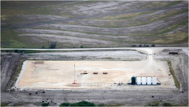
While we are talking about the oil field, we should probably talk about what the oil field is.  Upstream operations mostly take place at a wellpad.  Modern fracked wells require relatively large amounts of space, as shown in this picture on the left.   This is done to accommodate all the equipment needed to drill and complete a well.  "Completion" is a process whereby rock is perforated and stimulated (fractured & cleaned up). Once completed, a well enters production phase—as represented by the picture on below.

Oil wells are not static entities either; once drilled their production decreases over time.  Just as a juice box becomes harder and hard to drink from as you pull out all the fluid, the same is true with oil coming out of the ground.  After some time, usually a few months, artificial lift is installed to keep the oil flowing.  Artificial lift is a generic term for a pumping unit, but usually takes the form of a pump jack, like the ones below. Also on site you’ll find tanks for holding oil and water, heater treaters (basically a system to separate oil from water and associated gas), flare stacks, and of course an onsite generator.  While all of the equipment onsite is necessary, without a generator all activities on site come to a stop.


Early on, while the Bakken was being developed, (for political, legal, and strategic reasons) most wells were drilled with only one well on any given pad.  Today operators are doing what’s called infill drilling, where they packing together wells as densely as possible.  Without going into a detailed description of the geology and science of drilling and fracking, one thing is clear: there is more than one well per pad being drilled today.  This is important because each well typically needs 50-75kW of power.  Numbers vary, with as few as three wells per pad but we saw one pad with nine wells on site.  Each operator has their own secret number which is highly correlated to the reservoir engineering that is going on below the ground.
Kodiak Oil & Gas Corp
Howard Weil Energy Conference, March 2014
http://www.kodiakog.com/pdf/KOG_Mar2014.pdf


After the first six months (as shown from the chart on right), a typical well will be producing $30,000 in oil a day (or $1,250 an hour).  I think it is interesting to note that on that well pad with 9 pumpjacks, we saw one generator, which rented for roughly $20,000 a month.  Each hour of downtime from that generator at that wellpad amounted to $10k—and a good generator averages a day and a half of downtime a month.  More on this next time.

Monday, March 10, 2014

The Bakken—Part 1: Boomtown

Image source: UND EERC

The Dynamo Team went out to Williston, ND last month to see firsthand the shale revolution that is changing

the energy world.  The reason to come to Williston is that it is at the center of the action. Landing in Williston was uneventful, save that the airport was probably the size of our incubator, Greentown Labs.

A boomtown is an amazing place, where at first the world seems like any other you are familiar with, but after a while you realize it is actually different.  Very, very different. 


Getting out of the Airport, Williston seems like any other midwest American town of ~14,000 people: streetlights, cars, gas stations, and local restaurants that were never displaced by big national chains.  But once you drive half a mile beyond the airport, you notice the odd things.  There are far too many trucks on the road.  Not SUVs, but 18 wheelers, and cement trucks, and tankers—in fact, you barely see any other types of vehicles on the road.  These trucks always seemed to be on the road, morning or evening; we would later hear them screaming by as we tried to sleep in our hotel.


As you drive from the airport, along Highway 2, you see the roads are lined, not with strip malls like you would see in suburban America, but office buildings of service companies; names like Schlumberger, Baker Hughes, Cameron, Caterpillar, & Weatherford streak by in your peripheral vision.  Of the houses you did see, you wonder why the houses are so small and packed together in this mostly un-inhabited county.  You notice the flash of light from the sides of metal buildings still under construction, and you wonder why there needs to be so many trailer parks for this little town.  As you will later learn, Williston has the highest rent in the US, and some believe that the population of Williston swells to 75,000 people in the summer—and they are all here to work on drilling oil.   

We arrived at our hotel to find it was still under construction.  Workers were painting the walls and lining Ethernet as we checked in.  When we asked the front desk where we could grab some dinner, she exclaimed “Applebee’s just opened up down the street.”  As we drove to dinner (we opted for something more local than Applebee’s) we saw Pumpjacks right in town—an integral part of the urban landscape.  

We had arrived in a boomtown, where oil wells and buildings, services were being built out at a lightning pace, but where talent and the houses for them to live in could not be found fast enough.  We had arrived in a town where at every table sat groups of people with the word oil on their lips.  We had arrived in a town where something new and different was taking place; where people came to be a part of the tidal wave that would bend history.  

Monday, February 24, 2014

Getting Electricity from a Jet

After the Turbocore, there is a dynamo (or as we call it these days, a permanent magnet generator).  The generator that is attached to the Turbocore produces electricity at 1 kHz, much too fast for conventional equipment to use it, so we pass the power through a rectifier to make stable DC power across a DC link.  After the DC link, an inverter changes the power to a more standard form of AC power – in this case 60 Hz standard utility power - so that it can go into the grid, power a compressor, power a beam pump, or be used for other applications.  A DC converter could also be installed in lieu of the inverter for DC applications.  This is a typical power conversion architecture for microturbines.


While this architecture is a little more complex than your household Honda generator, it gives us product flexibility and reliability.  The DC link is electrically simple, and is a good place to create modularity in the engine.  Components on the left can be changed independently of components on the right.  This means it’s easier for us to cost effectively provide 120V 1-phase power or 3 phase 240V power or even 48 VDC by changing a few parts.  On the other side of things, it’s easier for us to make upgrades to the underlying hardware—the engine and the generator—without sacrificing electrical quality.  In fact, multiple inverters and multiple generators can be attached to both sides of the link, providing end users with a wealth of options for power.

While we are talking about electrical, and what that means for the end user, we do want to talk about why the Dynamo Turbocore has two turbines.  We could have gone with a single turbine: it’s cheaper, there are less parts and less engineering to be done with a single shaft engine.  However, we went with a split shaft design because we realized doing so would result in a more stable and more reliable engine whose performance would be less sensitive to changes in the application. 

A two-shaft engine has two main subsystems: the gas generator and the power turbines.  The gas generator includes the compressors, the combustion chamber, and the turbines that power the compressors; the remaining turbines are mechanically connected to an electric generator and are called power turbines.  There are three main advantages for doing this.

The first advantage of a two-shaft engine is that the second turbine, which spins the electric generator, can be designed to operate at a lower RPM, which results in less stringent performance requirements for the turbo-machinery, the electric generator and the power conversion unit.   This holds true for mechanical loads as well, which also see significant advantages from lower gear ratios and lower speeds.  

The second advantage is that the power turbine is a constant power device, which is exhibited as a significantly superior torque characteristic versus engine speed compare to a single-shaft engine.  For a single-shaft engine, the available torque decreases to zero as the speed of the engine drops; for a two-shaft engine, the available torque increases as the speed decreases.  The torque characteristic for a two-shaft engine t is also superior to that of a reciprocating engine, which has a relatively flat torque curve.  The torque advantage is important during back starting heavy loads. 

Lastly, the Turbocores are controlled to provide consistent power to the power turbine; the gas generator is essentially de-coupled from the power demands;  the gas generator can be throttled up and down faster and the compressor is not limited by the load on the turbine, and can generally operate near their efficiency point.  The control system can be more robust—there is less compromise between keeping the engine operational and preventing a brown-out.  Big power generating turbines where the load varies over time are generally of this split shaft configuration.  As a corollary split shaft engines are easier to start, with less thermal loading to the turbine system.

It is for these reasons and others we went to a split shaft design for our Turbocore product.

Tuesday, February 11, 2014

How The Turbocore Generates Power

At its very core, Dynamo is building turbo machinery.  A very simple device made complex by time and design.  The first turbines were built as early as Hero of Alexandria in the 1st century, yet with the advent of steam power, and the ever increasing need to do more work with less fuel in a tighter footprint, the turbine has become ever more complex. 

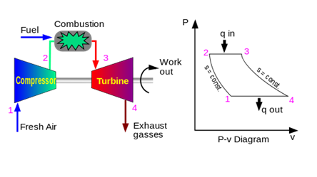
To explain how the Dynamo Turbocore works, we first must learn a basic fact about engines.  Engines do work, which is really a force over a distance (or a torque over an angle).  To get this useful work, typical engines complete a cycle (to allow you to get work over and over again).  By pushing on a fluid, adding heat, and then letting the fluid expand, and using that expansion to drive mechanical motion, some of the energy in the heat can be used to produce useful work—like lifting water or pushing a car. 


Gas Turbines do this in a very simple way.  Air is accelerated by a compressor wheel, and then slowed down in a stationary passage to convert velocity to static pressure.  Then heat is added in a combustion chamber, which expands the air and increases the volumetric flow rate.  Then the hot air is accelerated through a set of nozzles, and then a turbine gets pushed by this fast moving air, and pulls out some of the kinetic energy.  In the Dynamo Turbocore, there are two such turbines, the first one is used to power the compressor, and the second generates shaft power for us to use.  The compressor creates the push (force / area) while the air flowing through the engine is the volume (length * area).  For those of you keeping track, you will know that the volume passing through the turbine is greater than the volume flowing through the compressor—this is another way to interpret why heating the air creates more net power.


Gas turbines like the Turbocore can be made more efficient by adding multiple compressors or spinning the compressors faster to increase the pressure, and they can be made more powerful by using bigger compressors to flow more air (and volume) through the engine.

So that takes care of the mechanical portions of the engine.  But of course, this doesn’t explain how we take power from a rotating turbine and convert that into useful electricity—more on this next week.

Monday, January 6, 2014

Dynamo Value Proposition: Oil & Gas Customers

At Dynamo we are building a generator product for the broader market, but we are also paying special attention to the O&G market place.  We’ve spoken to over 25 companies and over 50 individuals about what they want and need in the marketplace.  The message is clear and consistent, with 15 terms that came up consistently.  Below is a word cloud of what customers were consistently looking for. 


We then took this input and determined what we could do best for our customers.  Some of these requirements are essential but unremarkable, such as reliability and safety, but others were non-trivial, like operating on lease gas and including built-in redundancy.  As a team we determined we could provide a great product but we were going to focus on three things.  We would provide a product that is fuel flexible, load following, and very easy to install, as these were the primary challenges found with installing other turbines in the field.

We listened, and have put special focus on building our turbine around a very flexible combustion system.  While our turbine is designed to be very fuel flexible, we decided we wanted to remove any engineering uncertainty and are including special fuel injectors and control system to enable the engine to operate on lease gas, irrespective of how sour or wet it will be.  One of the biggest concerns our customer have is the fact that lease gas composition changes over time.  Its energy content, pressure and temperature can change significantly compared to what typical gas turbines or natural gas reciprocating engines can handle on the order of minutes.  By designing mechanical buffering system and implementing control logic in our fuel delivery system, we’ve done away with those concerns.  There are no manual set points to worry about or governors to adjust.    Just plug in the fuel line, allow the gas to flow and start it up. 

There is also a need for a product that will be used continuously throughout the year, but must be able to respond to cyclic loads, like those from a pump jack.  Continuous operations are not a problem for a small turbine, the challenge is around cyclic loading.  To meet these challenges, we built our turbine differently from these rest of the microturbine industry.  We are utilizing what is called a split shaft design.  The part of our engine that generates power is separate from the primary engine, allowing for better load following, starting capability and tolerance to fuel variation. 

There are many things to mention in this post, but I will leave discussions about safety and emissions for another time.  The last thing I want to talk about is how we have made key decisions which will simplify installation and total installed costs for our customer.  Our product is small, about 1/3 the size of a traditional diesel generators, and small enough in most cases to fit on the back of a pickup truck.  You will still need a crane to lift the larger units off the bed, but unlike a reciprocating engine, a turbine generator does not need the same reinforced concrete pad to isolation vibration.  The overall footprint will be smaller, and the resulting cost and time required to set up the generator will be much less. 

These are just a few details on the myriad of nuanced design considerations we have put into our TurboCore products specifically for O&G customers.